Preliminary wind-load and structural analysis · 2026-09-08
Plywood slice model
A retained-data assessment of a 12 mm orthotropic plywood assembly under a 30 m/s atmospheric-wind field. Plywood strength and sampled buckling stability are checked for the stated model and load; this is not certification.
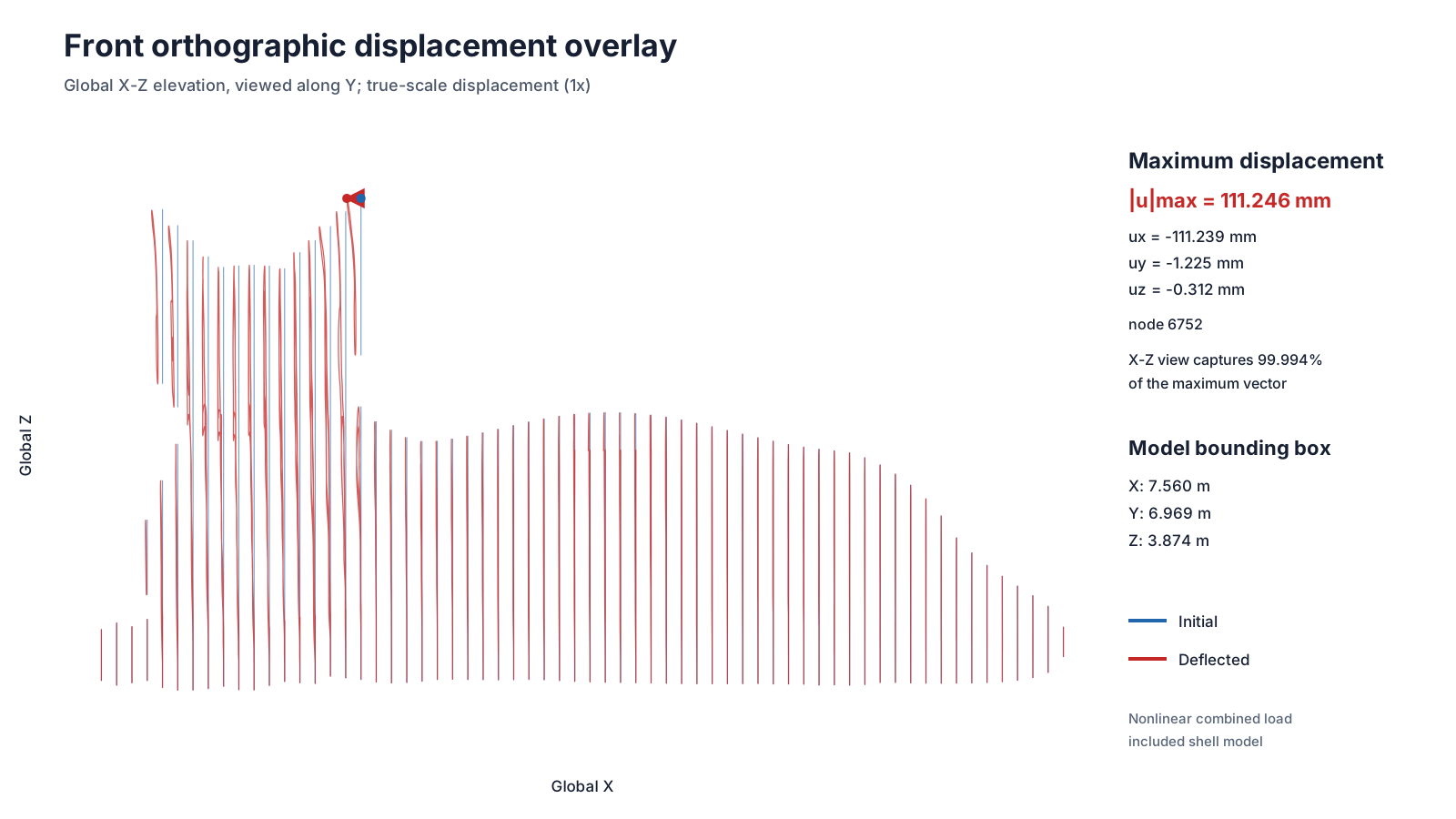
Current 60 mm-target nonlinear result at wind ×1.3 and full gravity. True-scale X–Z projection: original blue, deformed red; no display amplification.
Separate plywood strength checks
Action
Maximum ratio
membrane 1
0.5219
membrane 2
0.4164
bending 1
0.6212
bending 2
0.5684
panel shear 12
0.5936
rolling shear 23
0.7444
planar shear 31
0.9893
Each action is compared with its own characteristic strength. Limit 1.0; ratios are not summed. The governing margin is 1.075%, not an uncertainty bound.
Decision summary
PASSExact-load numerical checks: nonlinear completion, force/moment equilibrium, and qualified tangent. Not a new mesh-convergence claim.
PASSPlywood strength: agreed separate panel action checks; maximum ratio 0.989253. All elements included, no summed interaction. Scope and recovery limitations: Appendix D.
PASSBuckling stability. Accepted sampled-path check at ×1.3: two meshes, seven states each, plus the exact-load tangent. See Appendix H.
REPORTEDDeformation. No acceptance criterion was supplied.
Strength verdict applies to the agreed separate checks.
The supplied 24 mm mean field is multiplied by 1.3; gravity and strengths are unchanged. No CFD-field correction or connector-force clipping is applied; an upper bound is not proven.
3.890 kNsource CFD resultant, before structural exclusions
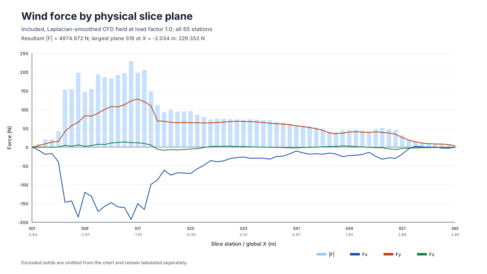
4.975 kNincluded wind resultant applied at 1.3×
111.2 mmh060 nonlinear maximum, unscaled
2.87%of 3.874 m analysis height
What was analysed
111 included plywood solids at 65 stations, joined by 420 rigid 108 mm connector systems. Seven unsupported solids and the one-sided connector Rf9D are excluded.
All shell nodes at global Z<200 mm are bonded; 57 intersecting rigid connector systems transmit compatible grounding constraints.
What the answer means
The h060 nonlinear endpoint governs the separate action/capacity checks. Buckling stability uses the accepted h090/h060 sampled-path evidence; additional meshes are not required. The model does not validate real construction or design wind.
Maximum sampled direction and conservative load chain
The direction screen used a tight XYZ box (24 × 13.44 × 7.68 m), 30 mm cells and 54 samples per angle. It selected 112.5° as the most prominent sampled direction. That direction was then rerun with a finer 24 mm lattice and expanded Y (24 × 20.16 × 7.68 m); only the completed finer run supplies the structural loads. 0° is +X, counter-clockwise toward +Y.
34333 development steps; 214 samples across 2 windows, 1.600 s total
Domain XYZ
24.00 × 20.16 × 7.68 m; Y only; X and Z unchanged from baseline
Force transferred to the structure
CFD cell sum
3.890 kN
After exclusions
3.827 kN
Analysis factor
×1.3
Applied XYZ
(-3.493, 3.542, 0.057) kN
Applied resultant
4.975 kN
Updated mean load. Projected drag 3.607 kN; -25.35% versus the original 30 mm screen. Resolution, Y extent and sampling/development changed together. This is not an isolated sensitivity or a proven design-wind upper bound.
The structural factor of 1.3 is the user-supplied wind safety multiplier. It is not derived from a gust spectrum, return period, wind standard, pressure coefficient, or partial-factor system. It does not divide the plywood strengths. drag_mean_N is a projection only and is never added to the XYZ vector.
Method 2 · orthotropic shell model and numerical verification
From voxel forces to a constrained plywood assembly
Validate 118 watertight STL solids
Smooth and conserve 136,543 cell vectors
Project to exact slice silhouettes
Mesh quadratic S6 shells and patches
Solve linear + NLGEOM endpoints
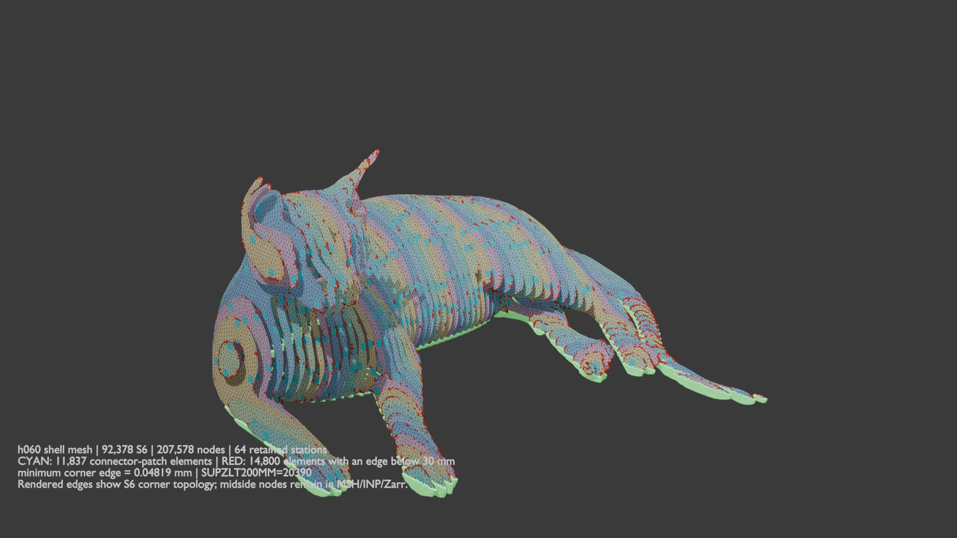
Fine native mesh preview. Cyan marks connector-patch elements; red marks elements containing a sub-30 mm corner edge. The numerical gate uses measured spacing and response change, not the nominal target label.h060 true-scale X–Z orthographic nonlinear overlay: initial blue, deflected red. Maximum unscaled displacement is 111.246 mm.
Source: UPM/WISA declaration of performance. E₃, transverse shear moduli, and Poisson ratios are declared modelling assumptions, not published product values.
Reused 60 mm-target mesh; exact new load
92,378 S6 elements; 207,578 nodes. Measured median S6 nodal interval 22.729 mm. The nominal 60 mm target is not the actual interval.
Native restart at wind ×1.125 and full gravity → unchanged-load equilibrium hold → monotonic continuation to ×1.3. Original mesh, couplings, ground bonds and material are retained. No scaled nonlinear stresses or full rerun.
4 accepted hold/continuation increments; 0 cutbacks; maximum 2 Newton iterations; solve/export 198.1 s.
The retained h090/h060 pair supplies the accepted stability verification. Current stresses and displacements come from the exact ×1.3 h060 endpoint.
Native software
FluidX3D not recordedcalculix_ccx 2.23calculix_cgx installed; banner unavailablegmsh 4.15.2-gitblender 5.2.1ffmpeg 9.0.1
Result · visual review, stresses, connectors, and limits
Fixed-model response at 1.3× retained mean wind
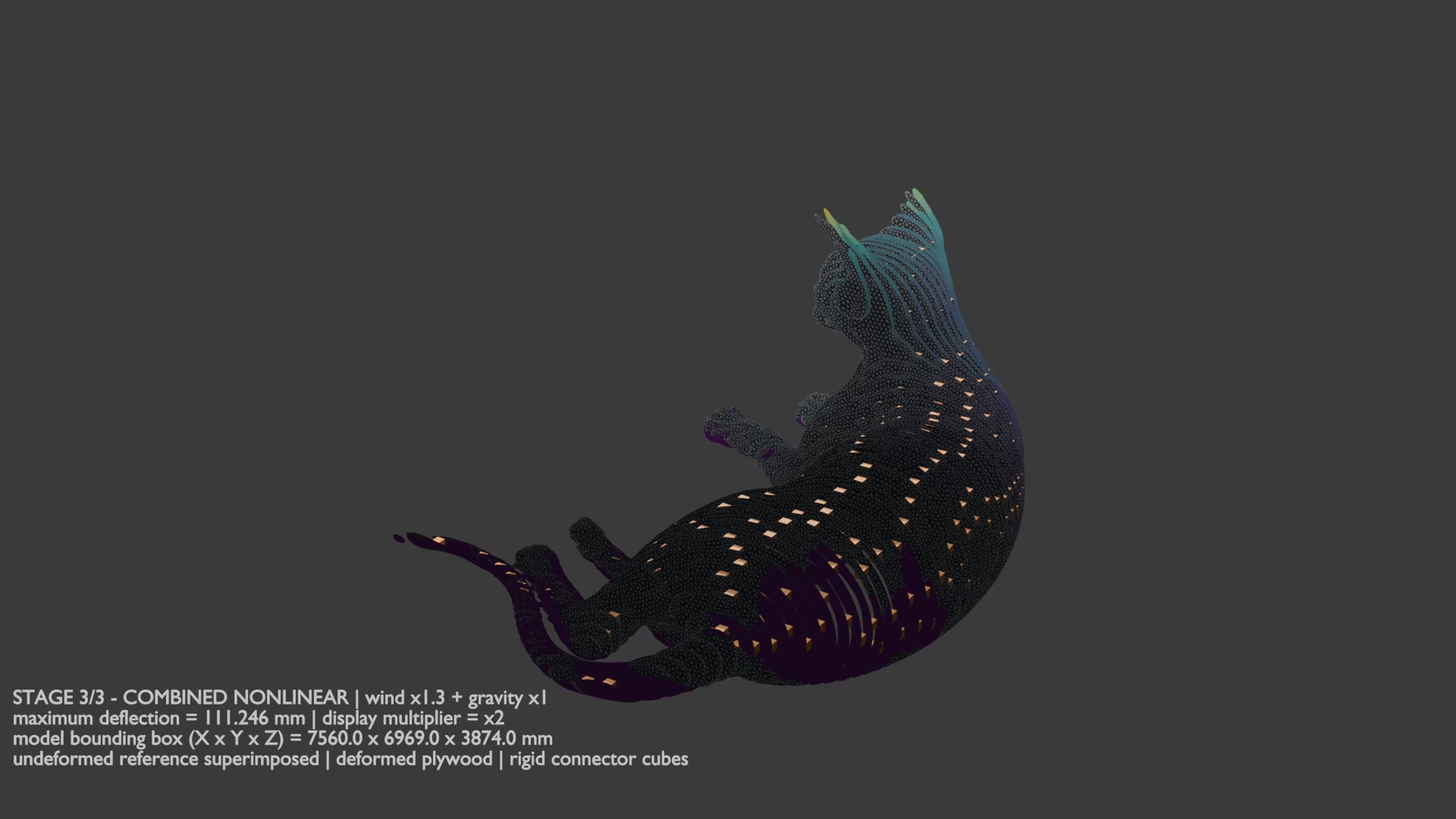
Current video: nonlinear solution, wind ×1.3 plus gravity. PDF: embedded current-load still replaces playback. 18-second, 1920×1080, 30 fps H.264 sequence: smoothed wind → native mesh → nonlinear response at ×2 display scale. Open the video directly (HTML package).
Latest static result (h060)
Maximum nonlinear displacement
111.246 mm
Maximum individual ratio
0.9893
Individual limits (nonlinear)
PASS
Material conclusion
PASS
Buckling stability (sampled path)
PASS
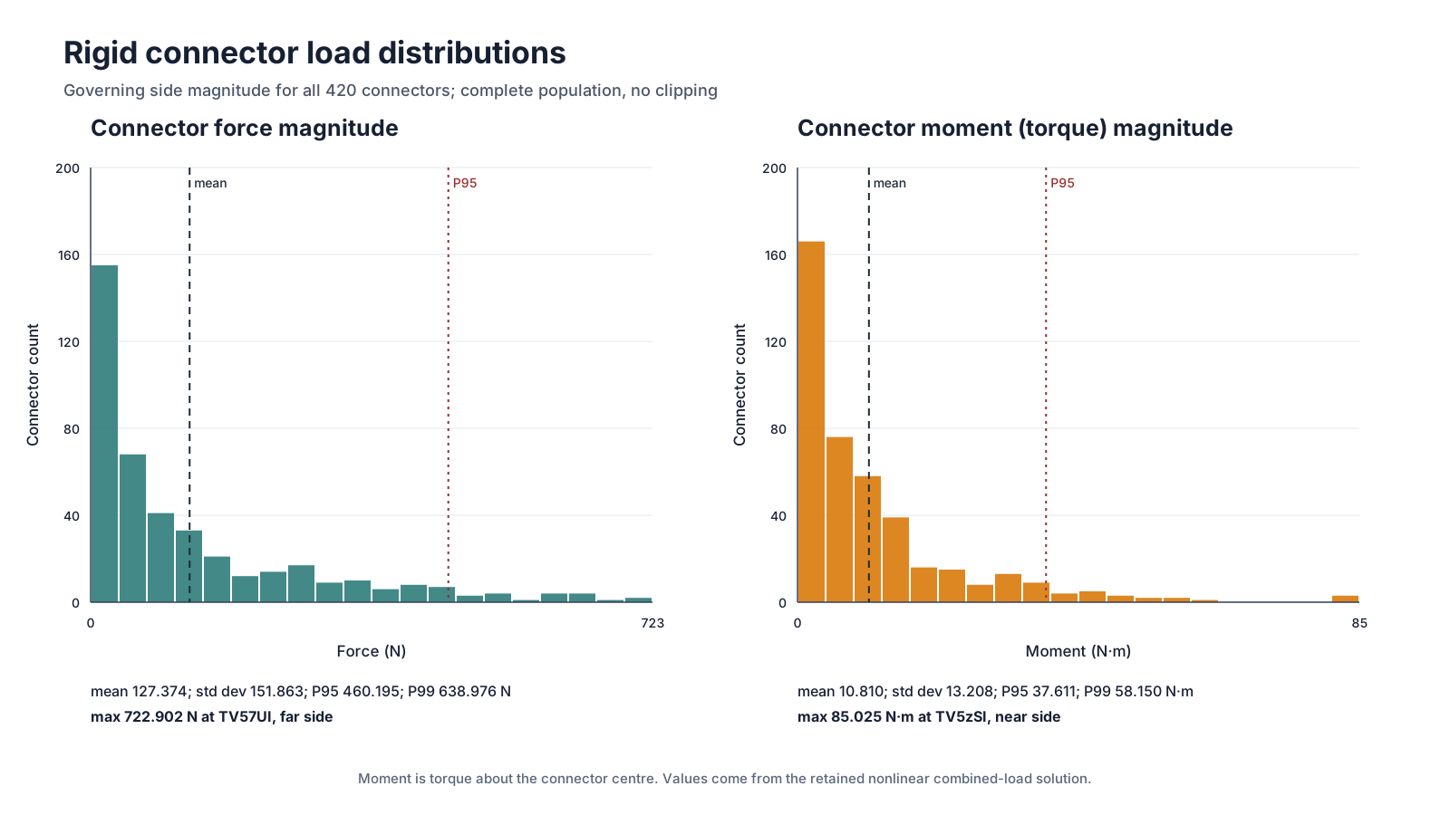
Nonlinear connector demand (420 systems)
Mean
σ
Maximum
Force
127.4 N
151.9 N
722.9 N TV57UI
Moment
10.81 N·m
13.21 N·m
85.02 N·m TV5zSI
Separate supplied capacities: 1000.0 N / 100.0 N m. Force PASS, moment PASS. These attachment wrenches are not adhesive, fastener, or cube stress checks.
Principal limitations
24 mm aerodynamic sheets represent physical 12 mm plywood; no validated high-Re wall model.
Mean loads only: no gust, peak, covariance, duration, return period, or code factors.
Ground bond, rigid connectors, homogeneous plywood, and one fixed grain realization idealise construction.
No joint/adhesive/fastener strength, foundation compliance, damage, moisture, or fatigue model.
Sampled buckling stability PASS; no continuous-path, untested-imperfection, ultimate-capacity or post-collapse guarantee.
Read with the appendices. Latest repaired-solver results and replacement list: Appendix H. Supplied connector capacities: 1000.0 N and 100.0 N m, separate checks. This web edition keeps the report figures and selected evidence records. Large solver arrays and native project files are outside the display bundle.
Appendix A · CFD model, full direction sweep, and render provenance
Wind-field construction and angular envelope
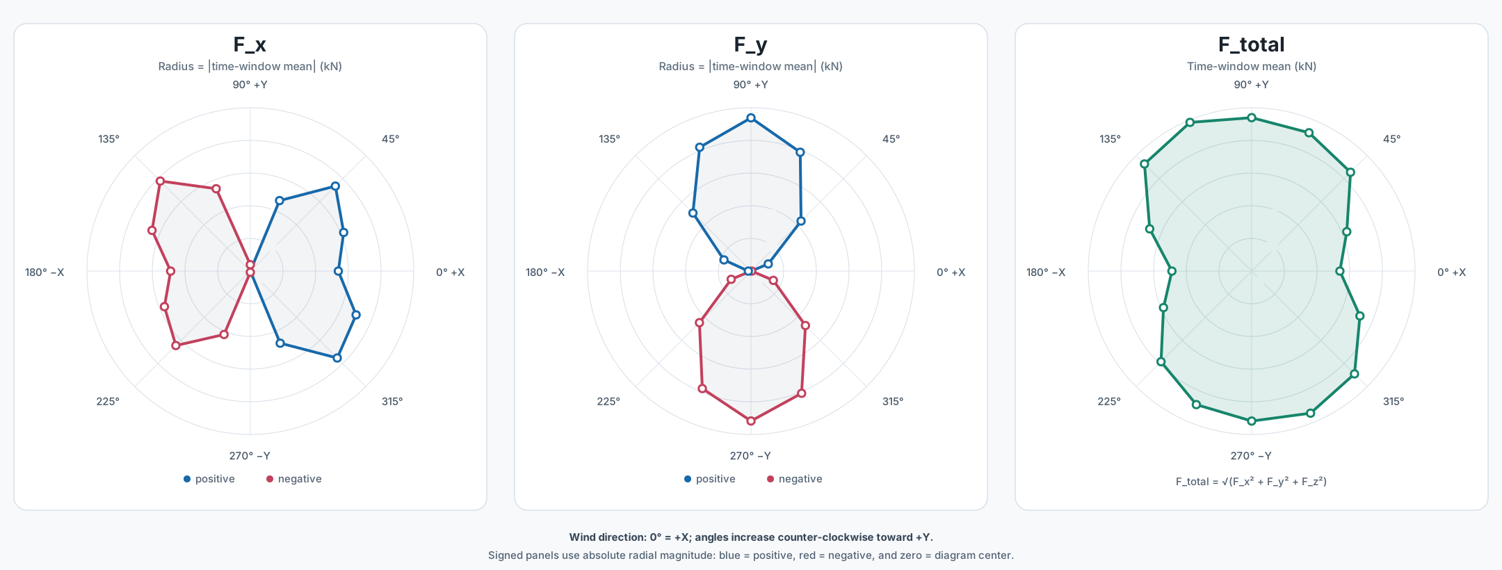
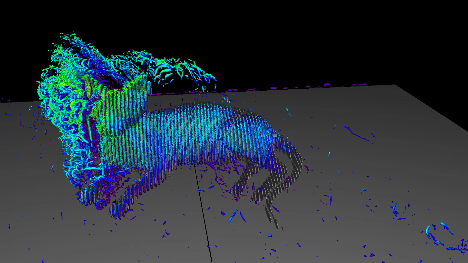
Frozen final instantaneous Q-criterion field from the current 112.5° case, step 60999. Camera-only visualization, not a mean-field or transient animation.Actual 214-sample cell-mean force surface, before structural Laplacian smoothing. Render-only framing shifts are not used for load mapping.
Physical setup
The precursor solves a neutral atmospheric boundary layer with U(z)=30·ln(z/0.02)/ln(10/0.02) m/s and no-slip ground. Its X–Z field is rotated into the requested angle and replicated across Y. Recovered U(10 m)=30.0176 m/s.
Momentum exchange is summed only on object cells marked TYPE_S|TYPE_X; ground is excluded. The resultant is a set of discrete forces, not continuous pressure tractions.
Numerical setup
D3Q19 lattice, SRT collision, FP16S distribution storage, equilibrium inflow/outflow, and Smagorinsky–Lilly SGS. Precursor 1000×5×480; object 1000×840×320.
The tight-box angular screen establishes the sampled direction ranking, not final force magnitudes. The finer expanded-Y calculation at 112.5° supplies the final field. The continuous angular maximum has not been measured.
Appendix B · spatial, boundary, collision, and lattice-headroom sensitivity
Earlier sensitivity evidence and remaining headroom
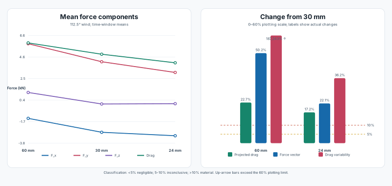
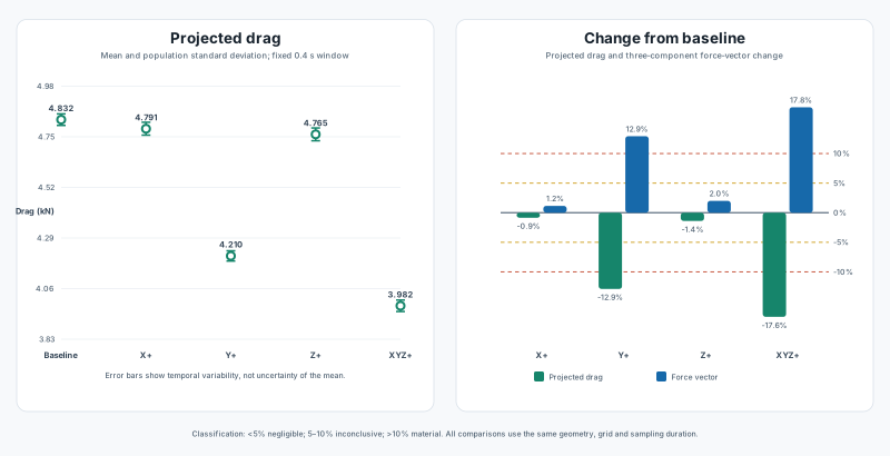
Earlier fixed-box short screens, not the current expanded-Y mean. The 24 mm screen lowers drag 17.18%; the 60 mm force history oscillates strongly.At 30 mm, Y expansion is the dominant individual boundary effect; combined XYZ expansion lowers drag 17.60%.
Resolution
Cell / grid
Drag
Δ
Assessment
60 mm 400x224x128
5.927 kN
22.66%
under-resolved oscillation
30 mm 800x448x256
4.832 kN
0.00%
original short screen
24 mm 1000x560x320
4.002 kN
-17.18%
short-screen refinement
Domain
Box
Drag
Δ
Baseline 24 x 13.44 x 7.68 m
4.832 kN
0.00%
X Expanded 36 x 13.44 x 7.68 m
4.791 kN
-0.86%
Y Expanded 24 x 20.16 x 7.68 m
4.210 kN
-12.88%
Z Expanded 24 x 13.44 x 11.52 m
4.765 kN
-1.39%
Combined Expanded 36 x 20.16 x 11.52 m
3.982 kN
-17.60%
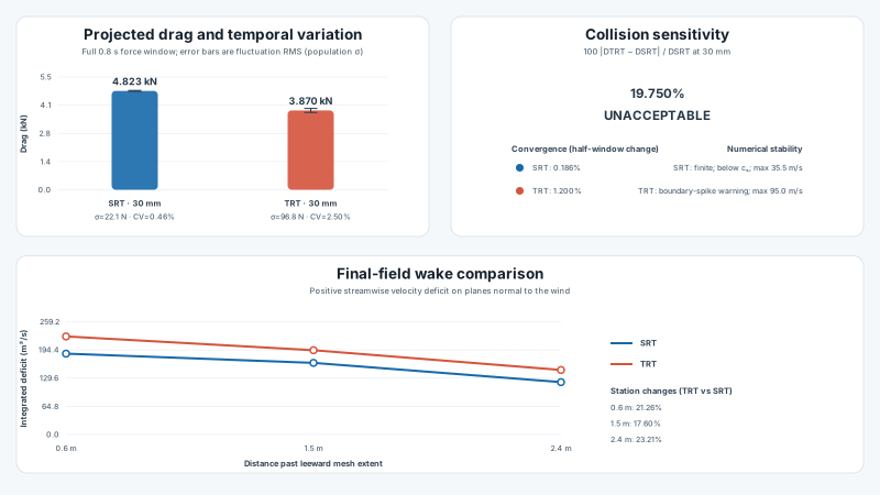
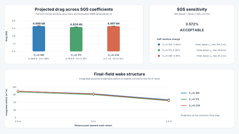
TRT changed drag by about 20% and produced boundary/field warning signs; it is rejected for this experiment.Cₛ=0.10–0.23 gives a 3.57% drag envelope; the low-Cₛ field itself has poor quality.
Load-field provenance: The tight-box angular screen selected 112.5°. The completed finer run at that direction uses a 24 mm lattice and a 24×20.16×7.68 m box with expanded Y. Its retained mean vectors supply the structural load, multiplied by ×1.3.
The tables above describe sensitivity evidence, not additional structural load cases. Direction screening and the completed final force field have distinct resolutions and sampling windows.
Appendix C · geometry, force mapping, connectors, exclusions, and supports
Structural idealisation and conservation checks
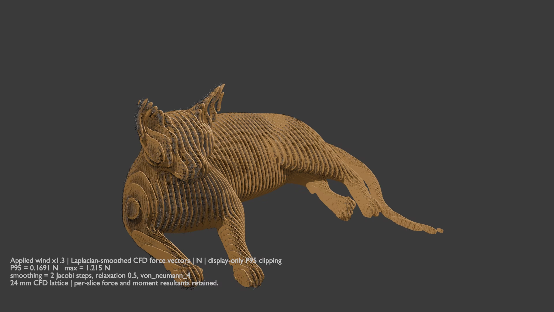
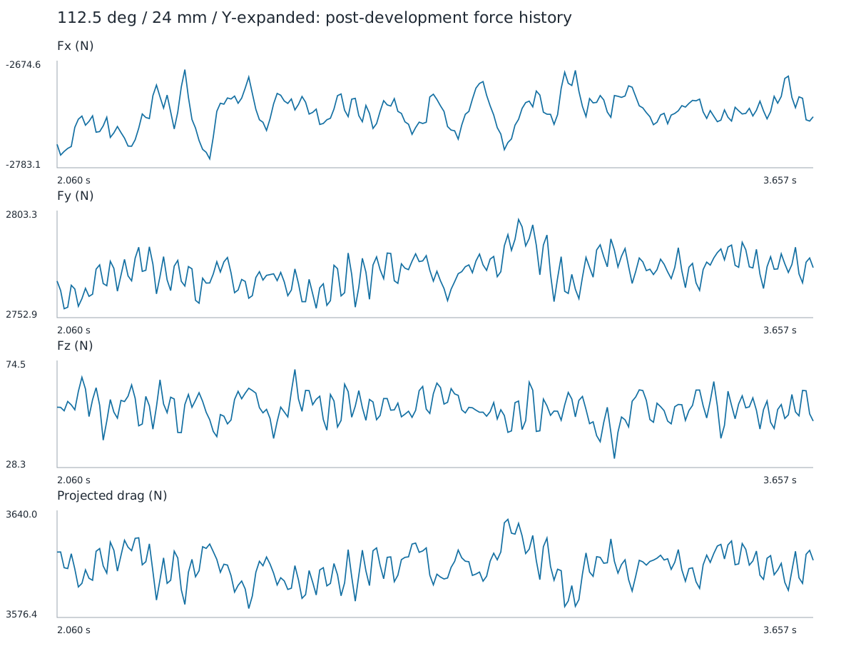
All 136,543 smoothed vectors are instanced in Blender and oriented by their actual XYZ direction. P95 length/colour clipping is display-only.Full force history for the current case, spanning both averaging windows. Structural loading uses the time-mean vector field, not its final instantaneous frame.
108×108×108 mm analytical rigid system; 0.4 kg static-equivalent weight at reference
Mapping and smoothing
Each lattice site is inverse-transformed into the original STL frame and assigned to its declared slice. Sites outside the silhouette are projected only within the cell YZ half-diagonal (16.971 mm); 28 sites moved, maximum 2.189 mm.
Two four-neighbour Y–Z Jacobi/Laplacian steps at relaxation 0.5 reduce neighbour RMS jump from 0.070 to 0.031 N. A constrained correction preserves force and origin moment per station.
Load conservation
Stage
Fx kN
Fy kN
Fz kN
|F| kN
|M₀| kN·m
All smoothed CFD cells
-2.7265
2.7747
0.0539
3.8904
—
Included, factor 1.0
-2.6869
2.7247
0.0442
3.8269
5.3895
Included, factor 1.3
-3.4930
3.5421
0.0574
4.9750
7.0063
Supports: every included S6 corner or midside node with global Z<0.200 m is fixed in six shell degrees of freedom. When a rigid patch overlaps that region, translations are fixed through the full-rank connector reference to avoid duplicate SPC/MPC equations; patch rotations retain shell SPCs. This is a locally bonded-ground idealisation, not a model of footing compliance.
Barycentric nodal distribution is nonnegative and conserves each force. Current ×1.3 endpoint support-reaction mismatch is 9.12e-05% in force and 1.77e-04% in moment about the origin.
Appendix D · plywood model, material axes, allowables, and interpretation
Orthotropic constants and characteristic-strength checks
CalculiX engineering constants
Constant
Used value
Basis
E₁
8.231 GPa
published bending stiffness
E₂
3.826 GPa
published bending stiffness
E₃
0.500 GPa
assumed
G₁₂
0.350 GPa
published plate shear
G₁₃
0.050 GPa
assumed transverse shear
G₂₃
0.040 GPa
assumed transverse shear
ν₁₂, ν₁₃, ν₂₃
0.25
assumed
Density
485 kg/m³
published mean
Thickness
12 mm
source geometry / product
Characteristic strengths used
Mode
Axis
MPa
Tension
1
9.5
Tension
2
8.9
Compression
1
15.8
Compression
2
14.8
Bending
1
20.6
Bending
2
13.3
Panel shear
1-2
3.5
Planar shear
3-1
1.0
Rolling shear
2-3
0.8
Whole-panel values for all seven bonded veneers of one 12 mm sheet, not individual veneer strengths. Do not multiply or divide by seven. Direction 1 follows face grain; 2 is transverse in-plane; 3 is through-thickness. Tension/compression selection is sign-dependent.
Material-axis policy: one PCG64 angle drawn uniformly on [0°,180°) for each physical station, seed 20260902; disconnected contours at a station share that angle. This is a single fixed realization, not a stochastic reliability analysis and not randomisation of the seven internal veneers.
How stresses are reduced
CalculiX expands each S6 shell to a three-dimensional C3D15 representation.
Top/bottom stresses are resolved into membrane and bending terms and transformed to station material axes.
Membrane tension/compression, directional bending, panel shear, rolling shear, and planar shear are divided by the characteristic strengths above.
Signed face tensors give m=(s⁺+s⁻)/2 and b=(s⁺−s⁻)/2. Shear uses total signed face stress once, including twist. Ratios are not summed; their maximum is a display statistic only.
Rule: an individual ratio >1 fails its nominal limit. All seven ratios ≤1, with qualified numerical prerequisites, give plywood strength PASS for the agreed separate panel checks. No summed interaction is used. A full ply-level or combined-load failure assessment is outside this verdict.
Largest h060 individual ratio over all elements: 0.9893. FRD nodal stresses are extrapolated/averaged; face samples do not bound interior transverse shear.
Only 1.075% below the assigned limit. This margin does not bound numerical or material-model uncertainty.
Material limitations
Characteristic values are not design allowables; no partial/material factor, duration, service class, moisture, temperature, or batch variability is applied.
One homogeneous shell law cannot reproduce both published axial and bending moduli or the actual veneer stack.
Missing E₃, G₁₃, G₂₃, and Poisson ratios are assumptions; current production robustness does not vary them.
Transverse shear is screened against characteristic strengths; progressive shear damage, local bearing, splitting, delamination, adhesive, fastener, and connector-cube failure are not modelled.
Ground and rigid-patch regions participate in the same maxima, percentiles and checks. All-element P99 is a convergence statistic, not a strength exemption; the separate checks use all-element maxima.
Primary product declaration. The report deliberately does not convert this preliminary characteristic check into a regulatory safety statement.
Appendix E · solver qualification, mesh convergence, stresses, and connector demand
Numerical evidence retained for the fixed model
Complete population; no clipping. Governing near/far/ground wrench selected once per connector.All 65 physical stations; sums use the included smoothed field at the 1.3 analysis factor.
Current nonlinear endpoint — wind ×1.3
Mesh
Maximum deflection
Largest separate ratio
Equilibrium
Tangent
h060
111.246 mm
0.989253
PASS
PASS
4 accepted hold/continuation increments, 0 cutbacks, at most 2 Newton iterations per increment. Force/moment equilibrium errors 9.12e-07 / 1.77e-06 (limit 0.001).
Separate plywood actions — all elements included
Action
Maximum stress / characteristic strength
membrane 1
0.521890
membrane 2
0.416357
bending 1
0.621233
bending 2
0.568444
panel shear 12
0.593623
rolling shear 23
0.744413
planar shear 31
0.989253
Qualified solver and constraints
CalculiX 2.23 with explicit constrained-tangent repair. Independent checks cover orthotropic plate response, rigid connector motion/reactions, positive and negative analytical stiffness, and restart equivalence.
Oriented nodal *COUPLING + *KINEMATIC; no *RIGID BODY. Assembly, stress and factorization use four threads; triangular substitution is serial.
Retained mesh quality
Native mesh validation passes. The h060 mesh retains 26,679 corner-edge instances below the nominal 30 mm floor; its minimum is 0.0482 mm. Exact contours and connector-patch intersections create these short local edges.
Global targets differ from actual nodal spacing. The h090/h060 comparison is explained in Appendix H; sampled stability acceptance does not claim convergence of every local stress peak.
Appendix F · software, artifacts, provenance, limitations, and next evidence
Reproducibility record and interpretation boundary
Software recorded by the run
Software
Version / commit
Role
FluidX3D
not recorded
D3Q19 LBM wind load
calculix_ccx
2.23
Synchronized SPOOLES: 4-thread assembly/factorization/stresses; serial triangular substitution; ARPACK eigenvalues
Gmsh .msh/.geo_unrolled; CalculiX .inp, .dat, .frd, logs, convergence and status files; Zarr v3 arrays with one Zstandard-compressed chunk per array.
Limitations that prevent a structural PASS
The source is a finite-window mean LBM field. Temporal stationarity does not bound spatial, domain or turbulence-model errors.
The current 1.3 multiplier is user-selected and does not represent gusts, turbulence peaks, a probability level, or a design standard.
The 112.5° direction was selected by a discrete tight-box angular screen; the completed finer run supplies its force magnitude, not a new continuous angular maximum.
CFD uses 24 mm cells; one aerodynamic cell is 2.00× the physical plywood thickness.
Separate panel-action checks (nonlinear): FAIL. Ply maximum-stress still lacks veneer data, layup and qualified ply/core stress recovery.
Conditional elastic stability: PASS. No damage, Riks continuation, or collapse-load prediction is included.
Rigid connectors, bonded ground, and characteristic plywood properties omit real joint/foundation behaviour and design factors.
The sibling FluidX3D experiment tooling was not fully committed; report hashes preserve evidence files, but its base commit alone is insufficient to reproduce every sweep.
Scope and further design evidence
The assessment uses the h060 endpoint for plywood and 1000 N / 100 N m connector checks, and the accepted h090/h060 sampled stability evidence. No additional mesh is required. Actual veneer/bond data, construction verification and design-wind validation would be needed for stronger claims outside this assessment.
Evidence hashes used by this HTML report
Input
SHA-256
structural force metadata /Users/vladimir/Documents/src/projects/cat-strength-calculator/stl/cfd_112p5_24mm_y_full/structural_cell_force_metadata.txt
CFD source force summary /Users/vladimir/Documents/src/projects/FluidX3D/results/cat_slice_wind_angle_112p5_30ms_box_y_expanded_grid_24mm_d2x1x1_full/force_summary.txt
The complete list, including copied visualizations, is retained in results/metadata/html_report.json. Structural configuration SHA-256: f7c4bf1001d755c506b12781fc8359b6cdab3ebb7a4c39005db58c9b449aeb90.
Appendix H · current assessment and mesh interpretation
Buckling stability at wind ×1.3
PASS — accepted sampled-path stability check.
The current h060 nonlinear solution includes full gravity and ×1.3 wind. Exact-load numerical status: PASS; constrained tangent: PASS. The retained h090/h060 meshes also passed all seven sampled checks up to ×1.5 wind. This is supporting stability evidence, not a change to the report's applied load.
What h090 and h060 mean
Mesh
Global target
S6 nodes
S6 elements
Median nodal interval
h090
90 mm
148,689
64,893
27.000 mm
h060
60 mm
207,578
92,378
22.729 mm
These are two discretizations of the same geometry, plywood law, grain realization, supports, connectors and force field—not different physical models. h090 uses a 90 mm global target and h060 a 60 mm target. Quadratic midside nodes, exact silhouettes and 108 mm connector patches set smaller local spacings. The CFD lattice is independently 24 mm.
h060 is the finer structural mesh and supplies the current stress, connector and deflection fields. No extra mesh or unfinished mesh case is part of the accepted report scope.
Retained sampled-path verification
Mesh
Passed checks
Maximum at verification load
h090
7 / 7
128.89 mm
h060
7 / 7
129.65 mm
At the ×1.5 verification endpoint, deflections differ by 0.59%. The largest shell/connector displacement change across all common sampled states is 1.288%, below the 5% gate. These verification-load deflections are not the current ×1.3 demand of 111.246 mm.
The seven states cover zero/half/full gravity and 25/50/75/100% of verification wind. Each requires force/moment equilibrium, a complete independent-DOF operator and positive qualified tangent stiffness. The exact ×1.3 endpoint supplies an additional check at the assessed load.
PASS applies to the accepted sampled, ideal-geometry buckling-stability check. It is not an ultimate buckling multiplier, proof of stability between every sampled state, untested imperfection coverage, or certification. Plywood and connector capacities are checked separately at the current load.
Latest nonlinear endpoint · h060 · wind ×1.3
Repaired-solver deformation and connector demand
Exact nonlinear endpoint, gravity plus 1.3× source wind; true-scale projection.
Force mean/std/max 127.37/151.86/722.90 N. Moment mean/std/max 10.81/13.21/85.02 N m. Separate force/moment capacity ratios: 0.7229 / 0.8502.
Separate plywood action
Maximum stress/strength ratio
membrane_1
0.521890
membrane_2
0.416357
bending_1
0.621233
bending_2
0.568444
panel_shear_12
0.593623
rolling_shear_23
0.744413
planar_shear_31
0.989253
Governing location: C032, element 28403, node 31632, positive face. XYZ (-1.9140, 0.4372, 0.7718) m.
All regions included; no action ratios added. Endpoint equilibrium: PASS. Separate force/moment limits: PASS / PASS. Face-node transverse shear is a panel screening value, not qualified ply/core through-thickness recovery. Reduction and source hashes.